Lab: Segment Routing Traffic Engineering (SR-TE)
Overview
This lab demonstrate Segment Routing Traffic Engineering (SR-TE) on Arista cEOS. It explores various use cases across multiple lab scenarios, highlighting how SR-TE can be applied to steer traffic, optimize paths, and validate traffic engineering behaviors.
Lab files including Containerlab topology are available on GitHub.
Learning Objectives
- Configure manually provisioned SR‑TE policies (on the headend router) with explicit and dynamic paths.
- Use BGP Color Extended Communities to steer traffic.
- Create primary and backup SR‑TE policies by adjusting IGP preference and cost.
- Enable S‑BFD monitoring for SR‑TE policies.
- Validate control plane and data plane operation.
- Remove the requirement for Binding‑SIDs.
Lab consists of following routers
pe1pe2pe3pe4p1p2ce1ce2
Key protocols used
- SR-MPLS with IS-IS in the core. IPv4 unnumbered and IPv6 link-local addresses are used on poit-to-point interfaces.
- BGP VPNv4 between PE routers.
- Seamless Bidirectional Forwarding Detection (S-BFD).
- IS-IS Flexible Algorithm (Flex-Algo).
Lab exercises
- Lab #1 – Primary SR-TE Policy with Explicit Path (Color-Based Steering)
- Lab #2 – Backup SR-TE Policy with Explicit Path and IGP Preference and Cost
- Lab #3 – Seamless Bidirectional Forwarding Detection (S-BFD) Monitoring for SR-TE Policies
- Lab #4 – Operating SR-TE Policies Without Binding-SIDs
- Lab #5 – SR-TE Policies with Dynamic Paths
Lab #1 – Primary SR-TE Policy with Explicit Path (Color-Based Steering)
- The VPNv4 prefix 8.0.0.0/24 is advertised by
pe3. - BGP Color Extended Community is used to steer traffic (automated steering) into an SR-TE policy; color value 30 is attached to the VPNv4 prefix 8.0.0.0/24.
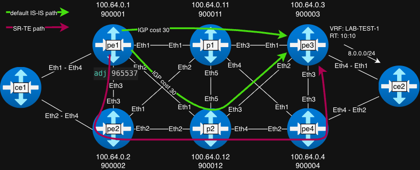
- SR-TE policy with explicit path label stack 965537 900012 900004 900003 is configured to forward traffic along the path
pe1->pe2->p2->pe4->pe3. - Label 965537 has been explicitly configured as an adjacency label on the
pe1interfaceEthernet3.
Configuration - prefix-list, route-map and BGP VRF on pe3. The following configuration propagates the VPNv4 prefix 8.0.0.0/24 along with a Color Extended Community, enabling SR-TE path steering on pe1:
pe3#sh ip prefix-list SET-COLOR
ip prefix-list SET-COLOR seq 10 permit 8.0.0.0/24

pe3#sh route-map SET-COLOR
route-map SET-COLOR permit 10
  Description:
  Match clauses:
    match ip address prefix-list SET-COLOR
  SubRouteMap:
  Set clauses:
    set extcommunity color 30

sh run sec bgp | b VRF-1
   vrf LAB-VRF-1
      rd 100.64.0.3:10
      route-target import vpn-ipv4 10:10
      route-target export vpn-ipv4 10:10
      network 8.0.0.0/24 route-map SET-COLOR
The Color Extended Community value 30 is correctly attached to the VPNv4 prefix 8.0.0.0/24 on pe3:
pe3#sh bgp vpn-ipv4 8.0.0.0/24 detail
BGP routing table information for VRF default
Router identifier 100.64.0.3, local AS number 65000
BGP routing table entry for IPv4 prefix 8.0.0.0/24, Route Distinguisher: 100.64.0.3:10
 Paths: 1 available
  Local
    - from - (0.0.0.0)
      Origin INCOMPLETE, metric -, localpref -, weight 0, tag 0, valid, local, best, redistributed (Static)
      Extended Community: Route-Target-AS:10:10 Color:CO(00):30
      Local MPLS label (VRF based): 116384
The SR-TE policy with an explicitly defined path toward endpoint 100.64.0.3 (color 30) is configured on pe1:
router traffic-engineering
   segment-routing
      rib system-colored-tunnel-rib
      !
      policy endpoint 100.64.0.3 color 30
         binding-sid 1000003
         !
         path-group preference 100
            segment-list label-stack 965537 900012 900004 900003
The adjacency label is explicitly configured on pe1 interface Ethernet3:
pe1#sh run int e3 | i label
   adjacency-segment ipv4 p2p label 965537
Verification of SR-TE policy on pe1:
pe1#sh traffic-engineering segment-routing policy endpoint 100.64.0.3 color 30
Endpoint 100.64.0.3 Color 30, Counters: not available
        Path group: State: active (for 01:49:56), modified: 00:39:30 ago
                Protocol: Static
                Endpoint provisioning: Static
                Originator: 0.0.0.0(AS0)
                Discriminator: 32769
                Preference: 100
                IGP metric: 0 (static)
                Binding SID: 1000003
                Path computation: Configured
                Explicit null label policy: IPv6 (system default)
                Segment List: State: Valid, ID: 3, Counters: not available
                Protected: No, Reason: The top label is not protected
                        Label Stack: [965537 900012 900004 900003], Weight: 1
                        Resolved Label Stack: [900012 900004 900003], Next hop: 100.64.0.2, Interface: Ethernet3
Traffic toward the VPNv4 prefix 8.0.0.0/24 is forwarded via the SR-TE policy as indicated by the IP routing table on pe1:
pe1#sh ip route vrf LAB-TEST-1 8.0.0.0/24

VRF: LAB-TEST-1
[omitted]
 B I      8.0.0.0/24 [200/0]
           via SR-TE Policy 100.64.0.3, color 30, label 116384
              via SR-TE tunnel index 3, weight 1
                 via 100.64.0.2, Ethernet3, label 900012 900004 900003
Data plane verification - ping from ce1 to ce2 (8.0.0.8):
ce1#ping 8.0.0.8 source lo0
PING 8.0.0.8 (8.0.0.8) from 7.0.0.7 : 72(100) bytes of data.
80 bytes from 8.0.0.8: icmp_seq=1 ttl=62 time=4.21 ms
80 bytes from 8.0.0.8: icmp_seq=2 ttl=62 time=2.84 ms
80 bytes from 8.0.0.8: icmp_seq=3 ttl=62 time=2.48 ms
80 bytes from 8.0.0.8: icmp_seq=4 ttl=62 time=2.61 ms
80 bytes from 8.0.0.8: icmp_seq=5 ttl=62 time=2.56 ms

--- 8.0.0.8 ping statistics ---
5 packets transmitted, 5 received, 0% packet loss, time 16ms
rtt min/avg/max/mdev = 2.481/2.940/4.213/0.647 ms, ipg/ewma 4.079/3.550 ms
Tcpdump captured on pe2 interface Ethernet3:
pe2#bash tcpdump -i eth3
19:59:42.162774 aa:c1:ab:aa:11:6a (oui Unknown) > aa:c1:ab:72:5c:34 (oui Unknown), ethertype MPLS unicast (0x8847), length 130: MPLS (label 900012, tc 0, ttl 63) (label 900004, tc 0, ttl 63) (label 900003, tc 0, ttl 63) (label 116384, tc 0, [S], ttl 63) 7.0.0.7 > 8.0.0.8: ICMP echo request, id 9, seq 2, length 80
19:59:42.166787 aa:c1:ab:aa:11:6a (oui Unknown) > aa:c1:ab:72:5c:34 (oui Unknown), ethertype MPLS unicast (0x8847), length 130: MPLS (label 900012, tc 0, ttl 63) (label 900004, tc 0, ttl 63) (label 900003, tc 0, ttl 63) (label 116384, tc 0, [S], ttl 63) 7.0.0.7 > 8.0.0.8: ICMP echo request, id 9, seq 3, length 80
19:59:42.170729 aa:c1:ab:aa:11:6a (oui Unknown) > aa:c1:ab:72:5c:34 (oui Unknown), ethertype MPLS unicast (0x8847), length 130: MPLS (label 900012, tc 0, ttl 63) (label 900004, tc 0, ttl 63) (label 900003, tc 0, ttl 63) (label 116384, tc 0, [S], ttl 63) 7.0.0.7 > 8.0.0.8: ICMP echo request, id 9, seq 4, length 80
19:59:42.174718 aa:c1:ab:aa:11:6a (oui Unknown) > aa:c1:ab:72:5c:34 (oui Unknown), ethertype MPLS unicast (0x8847), length 130: MPLS (label 900012, tc 0, ttl 63) (label 900004, tc 0, ttl 63) (label 900003, tc 0, ttl 63) (label 116384, tc 0, [S], ttl 63) 7.0.0.7 > 8.0.0.8: ICMP echo request, id 9, seq 5, length 80
Tcpdump on
pe2interfaceEthernet3shows the label stack 900012 900004 900003 116384. The adjacency label 965537 is popped bype1before sending tope2. Label 116384 corresponds VPNv4 label advertised bype3. Traffic flows along the SR-TE path as intended.
Lab #2 – Backup SR-TE Policy with Explicit Path and IGP Preference and Cost
- The
ce2router is now dual-homed to bothpe3andpe4, and the VPNv4 prefix 8.0.0.0/24 is advertised bype4. - BGP Color Extended Community is used to steer traffic (automated steering) into an SR-TE policy; color value 40 is attached to the VPNv4 prefix 8.0.0.0/24 advertised by
pe4. - SR-TE policy with label stack 965537 900012 900004 is configured to forward traffic along the path
pe1->pe2->p2->pe4. - An IGP preference of 115 with dynamic cost calculation is configured globally under SR-TE, affecting all policies. The SR-TE policy toward
pe3(color 30) is preferred over the policy towardpe4(color 40), by assigning a higher cost to the backup policy. - All other configuration elements remain unchanged from Lab #1.
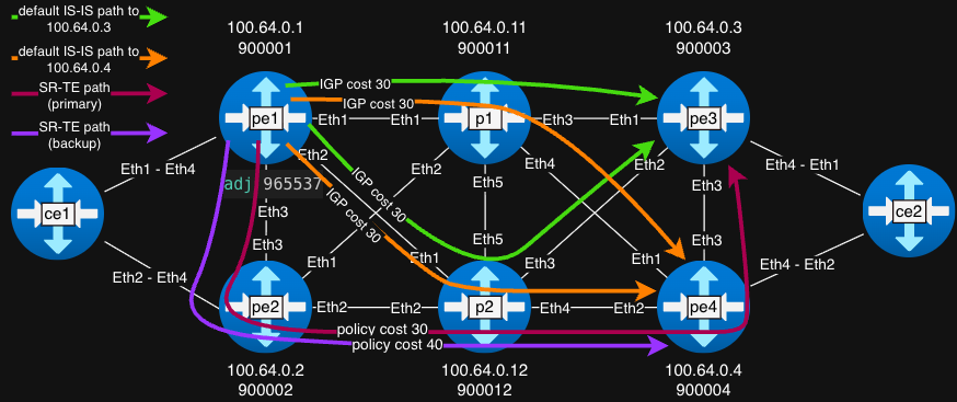
The backup SR-TE policy with an explicitly defined path toward endpoint 100.64.0.4 (color 40) is configured on pe1:
pe1#sh run sec color 40
router traffic-engineering
   segment-routing
      policy endpoint 100.64.0.4 color 40
         binding-sid 1000004
         !
         path-group preference 100
            segment-list label-stack 965537 900012 900004
Both SR-TE policies are installed in system-colored-tunnel-rib. Default IGP preference is 3, and IGP metric 0:
pe1#sh tunnel rib colored brief
Tunnel RIB: system-colored-tunnel-rib
 Endpoint         Color    Tunnel Type     Index(es)    Tunnel Preference    IGP Preference    IGP Metric   Metric Type
---------------- -------- --------------- ------------ -------------------- ----------------- ------------- -----------
 100.64.0.3/32    30       SR-TE Policy    0            35                   3                 0            metric
 100.64.0.4/32    40       SR-TE Policy    2            35                   3                 0            metric
The VPNv4 prefix 8.0.0.0/24 is learned from both pe3 and pe4, each carrying a different Color Extended Community:
pe1#sh ip bgp 8.0.0.0/24 detail vrf LAB-TEST-1
BGP routing table information for VRF LAB-TEST-1
Router identifier 10.1.7.1, local AS number 65000
BGP routing table entry for 8.0.0.0/24
 Paths: 2 available
  Local
    100.64.0.4 from 100.64.0.4 (100.64.0.4), imported VPN-IPv4 route, RD 100.64.0.4:10
      Origin INCOMPLETE, metric 0, localpref 100, IGP metric 0, weight 0, tag 0
      Received 00:08:27 ago, valid, internal, ECMP head, ECMP, best, ECMP contributor
      Extended Community: Route-Target-AS:10:10 Color:CO(00):40
      Remote MPLS label: 100000
      Rx SAFI: Unicast
      Tunnel RIB eligible
  Local
    100.64.0.3 from 100.64.0.3 (100.64.0.3), imported VPN-IPv4 route, RD 100.64.0.3:10
      Origin INCOMPLETE, metric 0, localpref 100, IGP metric 0, weight 0, tag 0
      Received 00:10:33 ago, valid, internal, ECMP, ECMP contributor
      Not best: ECMP-Fast configured
      Extended Community: Route-Target-AS:10:10 Color:CO(00):30
      Remote MPLS label: 100000
      Rx SAFI: Unicast
      Tunnel RIB eligible
 Not advertised to any peer.
Note
The maximum-paths 2 is configured under BGP to enable ECMP and allow PE routers to install and use two equal-cost paths. This configuration is used to demonstrate that both SR-TE policies can forward traffic toward the destination when all relevant path attributes are equal.
The routing table on pe1 confirms that both SR-TE policies are used to forward traffic toward 8.0.0.0/24:
pe1#sh ip route vrf LAB-TEST-1 8.0.0.0/24

VRF: LAB-TEST-1
[omitted]
 B I      8.0.0.0/24 [200/0]
           via SR-TE Policy 100.64.0.3, color 30, label 100000
              via SR-TE tunnel index 1, weight 1
                 via 100.64.0.2, Ethernet3, label 900012 900004 900003
           via SR-TE Policy 100.64.0.4, color 40, label 100000
              via SR-TE tunnel index 2, weight 1
                 via 100.64.0.2, Ethernet3, label 900012 900004
An IGP preference of 115 with dynamic cost calculation is configured globally under SR-TE, affecting all policies. The backup SR-TE policy is explicitly configured with an additional IGP cost of 10, ensuring it is less preferred than the primary policy.
Final configuration for the lab #2:
router traffic-engineering
   segment-routing
      rib system-colored-tunnel-rib
      igp-cost preference 115 metric dynamic
      !
      policy endpoint 100.64.0.3 color 30
         binding-sid 1000003
         !
         path-group preference 100
            segment-list label-stack 965537 900012 900004 900003
      !
      policy endpoint 100.64.0.4 color 40
         binding-sid 1000004
         igp-cost metric dynamic + 10
         !
         path-group preference 100
            segment-list label-stack 965537 900012 900004
   router-id ipv4 100.64.0.1
Colored Tunnel RIB state (After IGP Cost Adjustment):
pe1#sh tunnel rib colored brief
Tunnel RIB: system-colored-tunnel-rib
 Endpoint         Color    Tunnel Type     Index(es)    Tunnel Preference    IGP Preference    IGP Metric   Metric Type
---------------- -------- --------------- ------------ -------------------- ----------------- ------------- -----------
 100.64.0.3/32    30       SR-TE Policy    0            35                   115               30           metric
 100.64.0.4/32    40       SR-TE Policy    2            35                   115               40           metric
Detailed SR-TE policy view (Primary and Backup) - showing State status, IGP metric, Resolved Label Stack, etc.:
pe1#sh traffic-engineering segment-routing policy
Endpoint 100.64.0.3 Color 30, Counters: not available
        Path group: State: active (for 00:13:51), modified: 00:14:21 ago
                Protocol: Static
                Endpoint provisioning: Static
                Originator: 0.0.0.0(AS0)
                Discriminator: 32769
                Preference: 100
                IGP metric: 30 (dynamic-resolved)
                Binding SID: 1000003
                Path computation: Configured
                Explicit null label policy: IPv6 (system default)
                Segment List: State: Valid, ID: 1, Counters: not available
                Protected: No, Reason: The top label is not protected
                        Label Stack: [965537 900012 900004 900003], Weight: 1
                        Resolved Label Stack: [900012 900004 900003], Next hop: 100.64.0.2, Interface: Ethernet3
Endpoint 100.64.0.4 Color 40, Counters: not available
        Path group: State: active (for 00:13:51), modified: 00:14:21 ago
                Protocol: Static
                Endpoint provisioning: Static
                Originator: 0.0.0.0(AS0)
                Discriminator: 32769
                Preference: 100
                IGP metric: 40 (dynamic-resolved)
                Binding SID: 1000004
                Path computation: Configured
                Explicit null label policy: IPv6 (system default)
                Segment List: State: Valid, ID: 2, Counters: not available
                Protected: No, Reason: The top label is not protected
                        Label Stack: [965537 900012 900004], Weight: 1
                        Resolved Label Stack: [900012 900004], Next hop: 100.64.0.2, Interface: Ethernet3
Both VPNv4 prefixes now carry non-zero IGP metrics, with the lower metric being preferred:
pe1#sh ip bgp 8.0.0.0/24 detail vrf LAB-TEST-1
BGP routing table information for VRF LAB-TEST-1
Router identifier 10.1.7.1, local AS number 65000
BGP routing table entry for 8.0.0.0/24
 Paths: 2 available
  Local
    100.64.0.3 from 100.64.0.3 (100.64.0.3), imported VPN-IPv4 route, RD 100.64.0.3:10
      Origin INCOMPLETE, metric 0, localpref 100, IGP metric 30, weight 0, tag 0
      Received 00:19:11 ago, valid, internal, best
      Extended Community: Route-Target-AS:10:10 Color:CO(00):30
      Remote MPLS label: 100000
      Rx SAFI: Unicast
      Tunnel RIB eligible
  Local
    100.64.0.4 from 100.64.0.4 (100.64.0.4), imported VPN-IPv4 route, RD 100.64.0.4:10
      Origin INCOMPLETE, metric 0, localpref 100, IGP metric 40, weight 0, tag 0
      Received 00:17:05 ago, valid, internal
      Not best: IGP metric
      Extended Community: Route-Target-AS:10:10 Color:CO(00):40
      Remote MPLS label: 100000
      Rx SAFI: Unicast
      Tunnel RIB eligible
 Not advertised to any peer.
Traffic toward 8.0.0.0/24 is forwarded via the primary SR-TE path policy configured in lab #1:
pe1#sh ip route vrf LAB-TEST-1 8.0.0.0/24

VRF: LAB-TEST-1
[omitted]
 B I      8.0.0.0/24 [200/0]
           via SR-TE Policy 100.64.0.3, color 30, label 100000
              via SR-TE tunnel index 1, weight 1
                 via 100.64.0.2, Ethernet3, label 900012 900004 900003
Lab #3 – Seamless Bidirectional Forwarding Detection (S-BFD) Monitoring for SR-TE Policies
- S-BFD is configured globally on headend router
pe1and enabled under SR-TE path policies. - Reflector related S-BFD configuration is applied on routers
pe3andpe4.
Following configuration enables S-BFD globably on the headend router pe1, and activates S-BFD monitoring for both (primary and secondary) SR-TE path policies (configured in Lab #1 and #2):
pe1#sh run section bfd
router bfd
   sbfd
      local-interface Loopback0 ipv4
      initiator interval 1000 multiplier 3
router traffic-engineering
   segment-routing
      policy endpoint 100.64.0.3 color 30
         sbfd remote-discriminator 100.64.0.3
      policy endpoint 100.64.0.4 color 40
         sbfd remote-discriminator 100.64.0.4
Routers that act as S-BFD targets must be configured as S-BFD reflector. The following example shows the reflector configuration on pe3 (the same configuration model applies to pe4):
pe3#sh run section bfd
router bfd
   sbfd
      local-interface Loopback0 ipv4
      reflector min-rx 1000
      reflector local-discriminator 100.64.0.3
Verification - Both S-BFD sessions for the SR-TE policies are UP on the router pe1:
pe1#sh bfd peers
VRF name: default
-----------------
DstAddr                 MyDisc         YourDisc                 Interface/Transport            Type               LastUp       LastDown            LastDiag       State    Description
---------------- ---------------- ---------------- ----------------------------------- --------------- -------------------- -------------- ------------------- ----------- -----------
100.64.0.3          2095938501       1681915907       SR-Tunnel(140737488355330[2])       initiator       12/30/25 07:11             NA       No Diagnostic          Up              -
100.64.0.4          3702968690       1681915908       SR-Tunnel(140737488355329[1])       initiator       12/30/25 07:15             NA       No Diagnostic          Up              -
The following output shows detailed S-BFD session information toward endpoint 100.64.0.3:
pe1#sh bfd peers dest-ip 100.64.0.3 detail
VRF name: default
-----------------
Peer Addr 100.64.0.3, Tunnel ID 140737488355330(SR), Segment list ID 2, Type SBFD(initiator), State Up
VRF default, LAddr 100.64.0.1, LD/RD 2095938501/1681915907
Session state is Up and not using echo function
Hardware Acceleration: Async Off, Echo Off
Last Up 12/30/25 07:11:43.254
Last Down NA
Last Diag: No Diagnostic
Authentication mode: None
Shared-secret profile: None
TxInt: 1000 ms, RxInt: 1000 ms, Multiplier: 3
Received RxInt: 1000 ms, Received Multiplier: 3
Rx Count: 645, Rx Interval (ms) min/max/avg: 750/1001/877 last: 692 ms ago
Tx Count: 748, Tx Interval (ms) min/max/avg: 750/1001/875 last: 696 ms ago
Detect Time: 3000 ms
Sched Delay: 1*TxInt: 744, 2*TxInt: 3, 3*TxInt: 0, GT 3*TxInt: 0
Registered protocols: sr-te policy
Uptime: 09:25.87
Tunnel Info:  MPLS label stack: [965537 900012 900004 900003]
              MPLS EXP: 7
              IP DSCP: 192
Last packet:  Version: 1            - Diagnostic: 0
              State bit: Up         - Demand bit: 0
              Poll bit: 0           - Final bit: 0
              Multiplier: 3         - Length: 24
              My Discr.: 1681915907 - Your Discr.: 2095938501
              Min tx interval: 1000 - Min rx interval: 1000
              Min Echo interval: 0
Both SR-TE path policies are successfully monitored using S-BFD:
pe1#sh traffic-engineering segment-routing policy | i Color|State|SBFD
Endpoint 100.64.0.3 Color 30, Counters: not available
        Path group: State: active (for 00:01:19), modified: 00:02:01 ago
                Segment List: State: Valid, SBFD State: Up, ID: 1, Counters: not available
Endpoint 100.64.0.4 Color 40, Counters: not available
        Path group: State: active (for 00:01:18), modified: 00:02:01 ago
                Segment List: State: Valid, SBFD State: Up, ID: 2, Counters: not available
S-BFD reflector related state on pe3, the following output confirms that router pe3 is operating correctly as an S-BFD reflector:
pe3#sh bfd peers sbfd reflectors
VRF name: default
-----------------
DstAddr                 MyDisc         YourDisc       Interface/Transport            Type               LastUp       LastDown            LastDiag    State
---------------- ---------------- ---------------- ------------------------- --------------- -------------------- -------------- ------------------- -----
100.64.0.1          1681915907       2095938501                        NA       reflector       12/30/25 07:11             NA       No Diagnostic       Up
Data plane verification – A tcpdump capture on router pe2 interface Ethernet3 confirms that the S-BFD packets are forwarded within the SR-TE MPLS label stack, following the explicitly configured paths. The first packet is toward pe3 (label stack 900012 900004 900003), while the second packet is toward pe4 (label stack 900012 900003):
pe2#bash tcpdump -i eth3 ether proto 0x8847 -v
tcpdump: listening on eth3, link-type EN10MB (Ethernet), snapshot length 262144 bytes
07:27:50.539889 aa:c1:ab:e5:9b:ab (oui Unknown) > aa:c1:ab:b5:3b:17 (oui Unknown), ethertype MPLS unicast (0x8847), length 78: MPLS (label 900012, tc 0, ttl 254)
        (label 900004, tc 7, ttl 255)
        (label 900003, tc 7, [S], ttl 255)
        (tos 0xc0, ttl 1, id 0, offset 0, flags [none], proto UDP (17), length 52)
    100.64.0.1.51081 > localhost.localdomain.s-bfd: BFDv1, length: 24
        Sbfd, State Up, Flags: [Demand], Diagnostic: No Diagnostic (0x00)
        Detection Timer Multiplier: 3 (3000 ms Detection time), BFD Length: 24
        My Discriminator: 0x7ced7bc5, Your Discriminator: 0x64400003
          Desired min Tx Interval:    1000 ms
          Required min Rx Interval:      0 ms
          Required min Echo Interval:    0 ms
07:27:50.995323 aa:c1:ab:e5:9b:ab (oui Unknown) > aa:c1:ab:b5:3b:17 (oui Unknown), ethertype MPLS unicast (0x8847), length 74: MPLS (label 900012, tc 0, ttl 254)
        (label 900004, tc 7, [S], ttl 255)
        (tos 0xc0, ttl 1, id 0, offset 0, flags [none], proto UDP (17), length 52)
    100.64.0.1.51081 > localhost.localdomain.s-bfd: BFDv1, length: 24
        Sbfd, State Up, Flags: [Demand], Diagnostic: No Diagnostic (0x00)
        Detection Timer Multiplier: 3 (3000 ms Detection time), BFD Length: 24
        My Discriminator: 0xdcb6d172, Your Discriminator: 0x64400004
          Desired min Tx Interval:    1000 ms
          Required min Rx Interval:      0 ms
          Required min Echo Interval:    0 ms
The first packet follows the SR-TE path toward
pe3, with label stack 900012 900004 900003, whereas the second packet follows the SR-TE path towardpe4, with label stack 900012 900003.
S-BFD reflector responses (captured on pe1):
pe1#bash tcpdump -i eth1 src host 100.64.0.3 or 100.64.0.4 -v
tcpdump: listening on eth1, link-type EN10MB (Ethernet), snapshot length 262144 bytes
07:29:32.557804 aa:c1:ab:e7:eb:4f (oui Unknown) > aa:c1:ab:6e:75:d9 (oui Unknown), ethertype IPv4 (0x0800), length 66: (tos 0xc0, ttl 254, id 9030, offset 0, flags [DF], proto UDP (17), length 52)
    100.64.0.4.s-bfd > pe1.51081: BFDv1, length: 24
        Sbfd, State Up, Flags: [none], Diagnostic: No Diagnostic (0x00)
        Detection Timer Multiplier: 3 (3000 ms Detection time), BFD Length: 24
        My Discriminator: 0x64400004, Your Discriminator: 0xdcb6d172
          Desired min Tx Interval:    1000 ms
          Required min Rx Interval:   1000 ms
          Required min Echo Interval:    0 ms
07:29:33.163480 aa:c1:ab:e7:eb:4f (oui Unknown) > aa:c1:ab:6e:75:d9 (oui Unknown), ethertype IPv4 (0x0800), length 66: (tos 0xc0, ttl 254, id 26844, offset 0, flags [DF], proto UDP (17), length 52)
    100.64.0.3.s-bfd > pe1.51081: BFDv1, length: 24
        Sbfd, State Up, Flags: [none], Diagnostic: No Diagnostic (0x00)
        Detection Timer Multiplier: 3 (3000 ms Detection time), BFD Length: 24
        My Discriminator: 0x64400003, Your Discriminator: 0x7ced7bc5
          Desired min Tx Interval:    1000 ms
          Required min Rx Interval:   1000 ms
          Required min Echo Interval:    0 ms
The S-BFD responses from
pe3andpe4are captured onpe1’sEthernet1interface. These packets follow the IGP shortest path, as expected for S-BFD reflector replies.
Node failure testing – The Loopback0 interface on router p2 is shutdown, causing the Node-SID 900012 (along with other information) to be withdrawn from IS-IS LSP originated by p2. S-BFD detects the failure and moves both SR-TE policies to the Invalid state:
pe1#sh traffic-engineering segment-routing policy | i Color|State|SBFD
Endpoint 100.64.0.3 Color 30, Counters: not available
        Path group: State: invalid, modified: 00:05:50 ago
                Segment List: State: Invalid, SBFD State: Down, ID: 1, Counters: not available
Endpoint 100.64.0.4 Color 40, Counters: not available
        Path group: State: invalid, modified: 00:05:50 ago
                Segment List: State: Invalid, SBFD State: Down, ID: 2, Counters: not available
Traffic is forwarded via the IGP shortest path.
Lab #4 – Operating SR-TE Policies Without Binding-SIDs
- A Binding-SID is not required for the SR-TE policies in this lab, as traffic is steered locally on
pe1using the BGP Color Extended Community. - A specific configuration command is required to permit policies without Binding-SID.
- Binding-SIDs are removed from the SR-TE policies.
The Binding-SIDs 1000003 and 1000004 configured under SR-TE policies are installed in LFIB on pe1:
pe1#sh mpls lfib route traffic-engineering segment-routing policy
[omitted]
 ST    1000003  [1], SR-TE Policy 100.64.0.3, color 30
                via SR-TE tunnel index 1, pop
                 payload autoDecide, ttlMode uniform, dscpMode uniform, apply egress-acl
                    via 100.64.0.2, Ethernet3, label 900012 900004 900003
 ST    1000004  [1], SR-TE Policy 100.64.0.4, color 40
                via SR-TE tunnel index 2, pop
                 payload autoDecide, ttlMode uniform, dscpMode uniform, apply egress-acl
                    via 100.64.0.2, Ethernet3, label 900012 900004
The configuration command binding-sid specified-only disabled, applied under segment-routing submode, allows SR-TE policies to be configured without a Binding-SID. Once this option is enabled, the Binding-SID can be safely removed from the SR-TE policies:
pe1#conf t
pe1(config)#router traffic-engineering
pe1(config-te)#segment-routing
pe1(config-te-sr)#binding-sid specified-only disabled
pe1(config-te-sr)#policy endpoint 100.64.0.3 color 30
pe1(config-te-sr-policy)#no binding-sid
pe1(config-te-sr-policy)#policy endpoint 100.64.0.4 color 40
pe1(config-te-sr-policy)#no binding-sid
After removing the Binding-SIDs, they are no longer presented in the SR-TE policies, while both SR-TE policies remain active and operational:
pe1#sh traffic-engineering segment-routing policy
Endpoint 100.64.0.3 Color 30, Counters: not available
        Path group: State: active (for 00:15:36), modified: 00:02:15 ago
                Protocol: Static
                Endpoint provisioning: Static
                Originator: 0.0.0.0(AS0)
                Discriminator: 32769
                Preference: 100
                IGP metric: 30 (dynamic-resolved)
                Path computation: Configured
                Explicit null label policy: IPv6 (system default)
                Segment List: State: Valid, SBFD State: Up, ID: 1, Counters: not available
                Protected: No, Reason: The top label is not protected
                        Label Stack: [965537 900012 900004 900003], Weight: 1
                        Resolved Label Stack: [900012 900004 900003], Next hop: 100.64.0.2, Interface: Ethernet3
Endpoint 100.64.0.4 Color 40, Counters: not available
        Path group: State: active (for 00:15:37), modified: 00:02:10 ago
                Protocol: Static
                Endpoint provisioning: Static
                Originator: 0.0.0.0(AS0)
                Discriminator: 32769
                Preference: 100
                IGP metric: 40 (dynamic-resolved)
                Path computation: Configured
                Explicit null label policy: IPv6 (system default)
                Segment List: State: Valid, SBFD State: Up, ID: 2, Counters: not available
                Protected: No, Reason: The top label is not protected
                        Label Stack: [965537 900012 900004], Weight: 1
                        Resolved Label Stack: [900012 900004], Next hop: 100.64.0.2, Interface: Ethernet3
Binding-SIDs are also removed from the LFIB table on
pe1.
Lab #5 – SR-TE Policies with Dynamic Paths
- A new Flexible Algorithm with ID 128 and name BEST_EFFORT is defined on all routers in the topology. The Flex-Algo is configured to exclude links with administrative-group ID 33.
- An alias RED is created for administrative-group 33 on all routers.
- The new Flex-Algo (BEST_EFFORT) is advertised via IS-IS.
- Every router is configured with a new Flex-Algo Node-SID for BEST_EFFORT (Algo 128). Node-SIDs are derived from the base 900000 plus the router-specific offset 128xx, where
xxis the logical router ID. For example, the Node-SID for routerpe3is 912803. - Interfaces that must be excluded from SR-TE path computation are configured with administrative-group RED, as shown in the topology diagram.
- SR-TE policies with dynamic paths using the BEST_EFFORT Flex-Algo are configured on routers
pe3andpe4. - The VPNv4 prefix 7.0.0.0/24 is advertised from router
pe1with BGP Color Extended Community 10, enabling automated steering into the dynamic SR-TE policies.
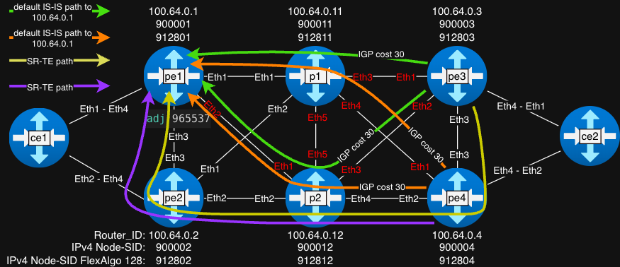
The Flex-Algo BEST_EFFORT with ID 128 must be configured on all routers in the topology. An alias RED is defined for administrative-group 33, which will be used to exclude specific links from path computation. The following configuration snippet is taken from router p1:
router traffic-engineering
   router-id ipv4 100.64.0.11
   administrative-group alias RED group 33
   !
   flex-algo
      flex-algo 128 BEST_EFFORT
         administrative-group exclude RED
The BEST_EFFORT Flex-Algo is advertised in IS-IS level-2 so that it is available for SR-TE path computation across the topology:
router isis LAB
[omitted]
   segment-routing mpls
      no shutdown
      flex-algo BEST_EFFORT level-2 advertised
Flex-Algo Node-SIDs are configured under the Loopback0 interface. This lab follows the Node-SID numbering logic described in Lab #5 summary:
interface Loopback0
   description Router_ID
   ip address 100.64.0.11/32
   ipv6 address 2000::100:64:0:11/128
   node-segment ipv4 index 11
   node-segment ipv4 index 12811 flex-algo BEST_EFFORT
   node-segment ipv6 index 211
   isis enable LAB
   isis passive
p1’s Flex-Algo Node-SID is 912811, derived from the base 900000 plus the Flex-Algo–specific offset 12811, where:
- 128 is the Flex-Algo ID (BEST_EFFORT)
- 11 is the logical router ID
Interfaces highlighted in red in the topology diagram are configured with administrative-group RED (ID 33). These links are therefore excluded from path computation by the BEST_EFFORT Flex-Algo. Example configuration from router p1:
p1#sh run sec int | sec traffic
interface Ethernet3
   traffic-engineering administrative-group RED
interface Ethernet4
   traffic-engineering administrative-group RED
interface Ethernet5
   traffic-engineering administrative-group RED
You can use the command
show isis database p1.00-00 traffic-engineeringto inspect the Traffic Engineering (TE) information advertised by routerp1in the IS-IS LSDB.
SR-TE policies toward endpoint 100.64.0.1 (Color 10) are configured on routers pe3 and pe4.
The keyword computation local must be configured under the path-group to allow the SR-TE policy to use a path resolved via Flex-Algo:
pe3#sh run sec endpoint
router traffic-engineering
   segment-routing
      policy endpoint 100.64.0.1 color 10
         path-group preference 100 computation local
            path segment-routing flex-algo BEST_EFFORT
SR-TE policy configuration on router
pe4is identical.
The SR-TE policy on pe3 is resolved via nhop 100.64.0.4 over interface Ethernet3, as expected:
pe3#sh traffic-engineering segment-routing policy
Endpoint 100.64.0.1 Color 10, Counters: not available
        Path group: State: active (for 00:01:54), modified: 00:02:51 ago
                Protocol: Static
                Endpoint provisioning: Static
                Originator: 0.0.0.0(AS0)
                Discriminator: 32769
                Preference: 100
                IGP metric: 0 (static)
                Path computation: Flex Algo BEST_EFFORT
                Explicit null label policy: IPv6 (system default)
                Segment List: State: Valid, ID: 3, Counters: not available
                Protected: No, Reason: The top label is not protected
                        Label Stack: [912801], Weight: 1
                        Resolved Label Stack: [912801], Next hop: 100.64.0.4, Interface: Ethernet3
Traffic is then forwarded to router p2 via pe4, as shown by the MPLS LFIB entry on pe4:
pe4#sh mpls lfib route 912801
[omitted]
 IP    912801   [1], 100.64.0.1/32, algorithm BEST_EFFORT
                via M, 100.64.0.12, swap 912801
                 payload autoDecide, ttlMode uniform, apply egress-acl
                 interface Ethernet2
On router p2, the Flex-Algo Node-SID 912801 is forwarded toward pe1:
p2#sh mpls lfib route 912801
[ommitted]
 IP    912801   [1], 100.64.0.1/32, algorithm BEST_EFFORT
                via M, 100.64.0.2, swap 912801
                 payload autoDecide, ttlMode uniform, apply egress-acl
                 interface Ethernet2
Finally, the label is popped on pe1, delivering the packet to the endpoint:
pe2#sh mpls lfib route 912801
[ommitted]
 IP    912801   [1], 100.64.0.1/32, algorithm BEST_EFFORT
                via M, 100.64.0.1, pop
                 payload autoDecide, ttlMode uniform, apply egress-acl
                 interface Ethernet3
Note
Final note for Lab #5
I did not initially plan to introduce Flex-Algo in this lab. Cisco IOS-XR supports SR-TE policies with dynamic paths computed locally on the headend (without Flex-Algo), where the headend calculates the path and installs a segment list that is then pushed onto packets (see slide 14).
I was unable to find an equivalent mechanism in Arista EOS. Based on my findings, Flex-Algo appears to be the only supported method to achieve dynamic SR-TE path computation in EOS. This effectively requires that Flex-Algo (including constraints and Node-SIDs) be configured consistently on all routers in the topology, which can be considered a limitation compared to the IOS-XR model.
That said, it is possible that an alternative approach exists and I may have overlooked it.